Bernoulli's Principle
Fundamentals of Fluid Dynamics
Bernoulli's Principle is a fundamental concept in fluid dynamics (the study of liquids and gases in motion). It describes the relationship between the pressure, velocity, and elevation in a moving fluid. It is named after the Swiss mathematician Daniel Bernoulli, who published the principle in his book Hydrodynamica in 1738.
The principle is based on the conservation of energy, stating that within a steady, incompressible, and inviscid (frictionless) flow, the total mechanical energy remains constant.
Core Idea: Where the speed of a fluid increases, the pressure within the fluid decreases, and vice versa.
The Principle Statement
Bernoulli's Principle can be formally stated as:
For an incompressible, inviscid fluid in steady flow, the sum of the pressure energy, kinetic energy, and potential energy per unit volume is constant along a streamline.
This is expressed mathematically by Bernoulli's Equation:
P + ½ρv² + ρgh = constant
Derivation of Bernoulli's Equation
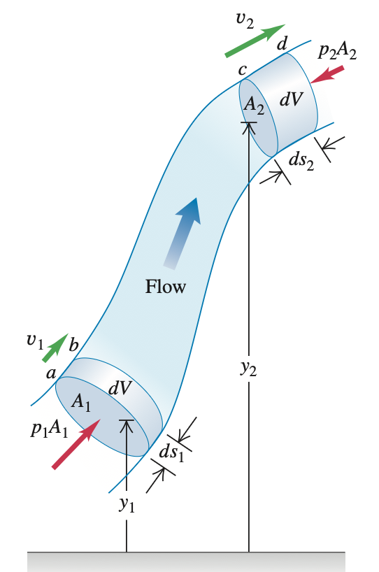
We can derive Bernoulli's equation by applying the work-energy theorem to a flowing fluid. To derive Bernoulli's equation, we apply the work-energy theorem to the fluid in a section of a flow tube. In the given figure, we consider the element of fluid that at some initial time lies between the two cross sections a and c. The speeds at the lower and upper ends are v1 and v2. In a small time interval dt, the fluid that is initially at a moves to b, a distance ds1 = v1 dt and the fluid that is initially at c moves to d, a distance ds2 = v2 dt. The cross-sectional areas at the two ends are A1 and A2, as shown.
Step 1: Continuity Equation
The fluid is incompressible; hence by the continuity equation, the volume of fluid dV passing any cross-section during time dt is the same. That is,
dV = A₁ds₁ = A₂ds₂
Step 2: Work Done
Let's compute the work done on this fluid element during dt. If there is negligible internal friction in the fluid (i.e., no viscosity), the only non-gravitational forces that do work on the element are due to the pressure of the surrounding fluid. The pressures at the two ends are p1 and p2.
Force at lower end: F₁ = P₁A₁
Force at upper end: F₂ = P₂A₂
The net work done (dW) on the element by the surrounding fluid during this displacement is therefore:
dW = P₁A₁ds₁ - P₂A₂ds₂
Equation (i)
The term P₂A₂ds₂ has a negative sign because the force at c opposes the displacement of the fluid.
Step 3: Kinetic Energy Change
The work done (dW) is due to forces other than the conservative force of gravity, so it equals the change in the total mechanical energy (kinetic energy plus gravitational potential energy) associated with the fluid element.
At the beginning of dt the fluid between a and b has volume A₁ds₁, mass ρA₁ds₁, kinetic energy KE₁ = ½ρ(A₁ds₁)v₁².
At the end of dt the fluid between c and d has kinetic energy KE₂ = ½ρ(A₂ds₂)v₂².
The net change in kinetic energy dK during time dt is:
dK = ½ρdV(v₂² - v₁²)
Equation (ii)
Step 4: Potential Energy Change
What about the change in gravitational potential energy? At the beginning of time interval dt, the potential energy for the mass between a and b is PE₁ = dm gy₁ = ρ dV gy₁.
At the end of dt, the potential energy for the mass between c and d is PE₂ = dm gy₂ = ρdV gy₂.
The net change in potential energy dU during dt is:
dU = ρdVg(y₂ - y₁)
Equation (iii)
Step 5: Combining Equations
Combining equations (i), (ii), and (iii) in the energy equation:
dW = dK + dU
P₁ + ½ρv₁² + ρgy₁ = P₂ + ½ρv₂² + ρgy₂
Equation (iv) - Bernoulli's Equation
Interpretation
This is Bernoulli's equation. It states that the work done on a unit volume of fluid by the surrounding fluid is equal to the sum of the changes in kinetic and potential energies per unit volume that occur during the flow. We may also interpret equation (iv) in terms of pressures. The first term on the right is the pressure difference associated with the change of speed of the fluid. The second term on the right is the additional pressure difference caused by the weight of the fluid and the difference in elevation of the two ends.
We can also express Eq. (iv) in a more convenient form as:
P + ½ρv² + ρgh = constant
Subscripts 1 and 2 refer to any two points along the flow tube, so we can write P₁ + ½ρv₁² + ρgh₁ = P₂ + ½ρv₂² + ρgh₂.
Note that when the fluid is not moving (so v₁ = v₂ = 0), equation (iv) reduces to the pressure relationship we derived for a fluid at rest.
Work Done on the Fluid Element
The net work done (Wnet) on the fluid element by the surrounding pressure forces as it moves is equal to the change in its mechanical energy.
Work at Point a (input)
W₁ = F₁⋅ds₁ = (P₁A₁)⋅ds₁
Work at Point b (output)
W₂ = − F₂⋅ds₂ = (P₂A₂)⋅ds₂
(negative because the force is opposite to the displacement)
Net Work Done
Wnet = W₁ + W₂ = (P₁A₁)⋅ds₁ - (P₂A₂)⋅ds₂
Since the fluid is incompressible, the volume that enters at point a (A₁ds₁) must equal the volume that exits at point 2 (A₂ds₂). Let's call this volume dV.
Wnet = P₁dV − P₂dV
Change in Mechanical Energy
This net work done must result in a change in the kinetic and potential energy of the fluid element.
Change in Kinetic Energy (ΔKE)
ΔKE = ½m₂v₂² − ½m₁v₁²
The mass m = ρdV, so:
ΔKE = ½ρdV(v₂² − v₁²)
Change in Potential Energy (ΔPE)
ΔPE = mgy₂ − mgy₁
Or, ΔPE = ρdVgy₂ − ρdVgy₁
ΔPE = ρdVg(y₂ − y₁)
Apply the Work-Energy Theorem
According to the theorem: Wnet = ΔKE + ΔPE
Substitute the values:
P₁dV − P₂dV = ½ρdV(v₂² − v₁²) + ρdVg(y₂ − y₁)
Divide the entire equation by dV:
P₁ − P₂ = ½ρv₂² − ½ρv₁² + ρgy₂ − ρgy₁
Now, rearrange the terms so that all quantities related to point a are on one side and point b on the other:
P₁ + ½ρv₁² + ρgy₁ = P₂ + ½ρv₂² + ρgy₂
This shows that the sum is the same at both points a and b. Therefore, it is constant along the streamline.
P + ½ρv² + ρgy = constant
Key Concepts and Simplifications
Static Pressure (P)
The actual thermodynamic pressure of the fluid. It's what we would feel if we were moving along with the fluid.
Dynamic Pressure (½ρv²)
The pressure exerted due to the fluid's motion.
Hydrostatic Pressure (ρgh)
The pressure due to the weight of the fluid above a point. For gases (like air), this term is often negligible over short distances because their density is low.
Simplified Form for Horizontal Flow
P + ½ρv² = constant
If height changes are negligible (y₁ ≈ y₂), the equation simplifies to this form, which is the most common form used for explaining lift and other aerodynamic phenomena. It clearly shows the inverse relationship between pressure and velocity.
Applications of Bernoulli's Principle
1. Airplane Wing (Aerofoil)
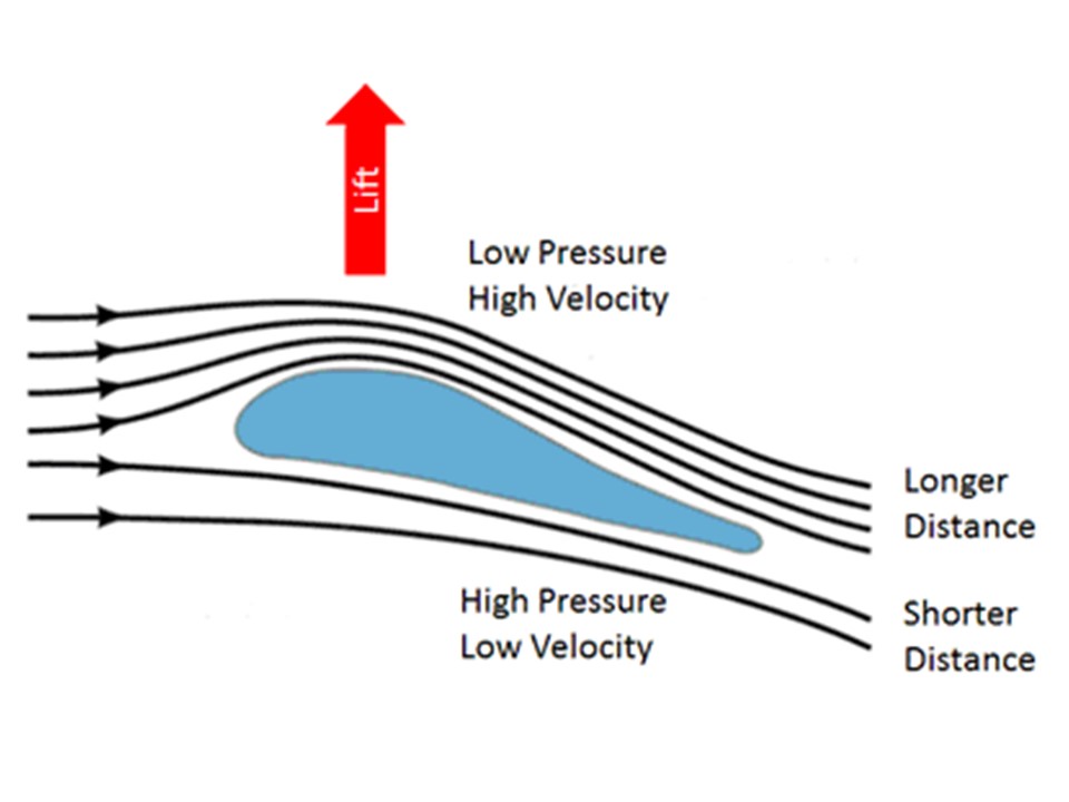
This is the most famous application. The shape of an airplane wing is designed so that air flowing over the top has to travel a longer distance than air flowing underneath. To do this in the same amount of time, the air on top must move faster.
According to Bernoulli's Principle:
- Faster air on top → Lower pressure.
- Slower air below → Higher pressure.
This pressure difference creates an upward force called Lift.
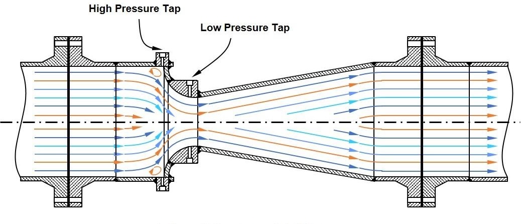
2. Venturi Effect
When a fluid flows through a constricted section of a pipe, its speed increases. Bernoulli's Principle tells us that this increase in speed results in a decrease in pressure. This phenomenon is known as the Venturi Effect.
Applications:
- Carburetors: In old car engines, air flows through a venturi, pressure drops, and this draws fuel into the air stream.
- Atomizers: Perfume or spray paint bottles use this. Blowing air across a tube creates low pressure, sucking the liquid up and breaking it into a fine spray.
- Venturi Meters: Used to measure the flow rate of fluids in pipes.
3. Bunsen Burner
The gas flows through a jet at high speed, creating a region of low pressure. This draws in (entrains) air through the air holes, which mixes with the gas for efficient combustion.
4. Why a Curved Ball Curves (Magnus Effect)
When a ball (like in soccer or baseball) spins, it drags some of the air around with it.
- On the side where the spin direction and airflow are the same, the air moves faster → lower pressure.
- On the opposite side, the motions are opposed, so the air moves slower → higher pressure.
The net force pushes the ball in the direction of the low pressure, causing it to curve.
5. Danger of Standing Near a Moving Train
When a high-speed train passes by, it pushes air along with it, creating a region of high-velocity, low-pressure air next to you. The higher-pressure air on your other side can push you towards the train, which is extremely dangerous.
Common Misconceptions & Important Notes
"Faster Flow Requires Less Time" Misconception
A common but incorrect explanation for wing lift is that the air over the top and bottom must "meet up" at the trailing edge at the same time. There is no physical law requiring this. The real reason for the velocity difference is that the wing's shape and angle of attack direct the airflow downward (a process that involves Newton's 3rd Law as well as Bernoulli's Principle).
It's Not a Standalone Law
Bernoulli's Principle is a consequence of energy conservation. It is not a standalone "cause" but a description of a relationship.
Assumptions are Critical
The derivation assumes an ideal fluid (incompressible, inviscid, steady flow). Real fluids have viscosity, which causes friction and energy loss (e.g., drag). However, for many situations like airflight at subsonic speeds, Bernoulli's Principle provides an excellent approximation.
Summary
Principle
In a moving fluid, an increase in speed occurs simultaneously with a decrease in pressure.
Equation
P + ½ρv² + ρgh = constant
Basis
Conservation of Energy for a flowing fluid.
Key Application
Lift on an airplane wing due to pressure difference created by different airflow velocities.
Other Applications
Venturi meter, carburetor, spinning ball, Bunsen burner.


0 Comments